Sunday, April 6, 2014

Bench Variable Power Supply

I have been wishing for a bench power supply for quite some time. Part of the problem is you need one to be able to make one. So I decided to cheat and make one the easy way. It is also the proper size for my limited work area.

I still intend to make a proper one with current limiting and a few more amps, but this will  help in  the mean time.
Variable 1.5 to 30V 3 amp supply, No current limiting. Driving a drill spindle.

The local electronics parts house stocks a few of the popular Chinese modules. So I bought a box and some modules:

The layout. Amp meter requires separate supply.

The modules from top to bottom:
Digital DC Voltmeter 2.5-30V red
DC AMP METER DC 0-10A 2.5-30V
DPDT switch for input and battery on/off
LM317 based variable supply 
  Voltage Regulator AC/DC 1.25-37V max 2.2A
  overload and short protected
Banana plugs and 9v battery
not shown 19V DC old laptop supply

Links to similar:
http://www.tinydeal.com/yb27-dc-33-30v-led-digital-voltmeter-led-car-voltmeter-p-105975.html

http://www.tinydeal.com/yb27va-2-in-1-dc-0-100v-10a-led-digital-voltmeter-ammeter-p-107011.html

http://www.aliexpress.com/item/1pc-new-AC-DC-to-DC-LM317-power-Continuous-adjustable-Voltage-regulator-With-protection-free-shipping/1121236182.html

http://www.aliexpress.com/item/electric-tools12V-24V-Mini-PCB-Drill-Press-mini-saws-burnishing-chuck-Electric-drill-bits-0-6/1115717842.html

While looking for the sample link for the mini drill I saw many like I wish I had found! This one will drill holes in PCB but the runout is to big for milling and the collet is real trash. A 0.8mm drill bit fits with considerable force.

Wednesday, March 26, 2014

Dreaming of a CNC Something...

I decided I needed these stepper motors... It started when I saw the instructables page for
Easy-to-Build-Desk-Top-3-Axis-CNC-Milling-Machine nbsp;. I started dreaming of ways to make my own PCBs with SMD components. I am not a very patient guy when it come to hobbies and experiments, so mailing off eagle files and expecting the boards to find me on the boat just doesn't sound plausible.

I started the search for a CNC mill with a resolution for SMD parts, then I discovered the inkjet transparencies and photo-resist so there was no need for a mill.... but I keep forgetting that part.

I found the steppers in an electronics place accross on the mainland from Penang, in Butterworth, Destiny Electronics. Prices are not that good, but he has lots of stuff in stock! When I went for the photo sensitive board stock (booth single sided and double sided Kinsten- from Tiawan) I picked up a couple stepper motors too.
So this is the test setup.

Clockwise:
Stepper is a 17PM-J319 fairly popular in the surplus market but very little in the way of documentation. I believe it is a 1.8 degree, 8 volt, 6 wire bi-polar (could wire it as uni-polar I think too)
Ardunio UNO clone, davilino from Seeed Studios
L298 motor driver fresh from China
And last a LM317 based 3 amp variable power supply also fresh from China surplus
These I picked up at the parts store here in Penang so no great price there either. Places like tinydeal.com and e-bay have lots of these making me wish Paypal would ship to Malaysia. But then I'd be broke.

Inkjet and Positive Resist Photo Artwork

I just discovered that it is possible to print on transparency film with an inkjet and use photo-sensitive pre-sensitized boards for custom PCBs. This is my first try.

I begged a few scraps from the local parts store here in Penang, Malaysia. I searched all over for inkjet transparencies then discovered I have a pack (20 sheets) that are at least 5 years old already on the boat! So the only thing left is the developer. It should be about 6% sodium hydroxide, or caustic soda. After a few failed attempts to purchase it in grocery stores and pharmacies, I headed for "The Chemical Man". Sure enough he had it by the kilo. since I only wanted enough for a few trial boards he finally sold me 15 grams for RM1, about $0.32 USD!

 
The board is much better than the focus of my phone camera


A better photo with the artwork

Now to the process. I wasn't sure my new HP inkjet printed dark enough, so I printed two copied of the board. This LEDTester was the quickest board to get ready that I had. I was in a hurry to find out if it really worked. I pulled one of the glass plates from the oil lamp in the fore-peak and taped the printout down. Then taped the second copy directly over it. Next came the pre-sensitized PCB trimmed to fit so as not to waste much if it did work. I exposed it in the sun, 5:00PM a little cloudy. As a test I covered thirds at a time and exposed 1 minute each so the result was one end got 3 minutes, the middle 2 and the other end only 1 minute exposure. I could hardly tell the difference, but maybe the 2 minute was the best.

Next to the developer. I forgot to mix it ahead, so I covered the exposed board and got to mixing. Since I bought 15 grams and the suggested ratio is 6 grams in a litre of water (6% solution) I estimated a little less than one 6th of what I had and put in an old pickle jar about 700ml. I stirred and stirred! There must be NO particles or crystals of caustic soda floating around or it will disolve everything off the board they say.

OK in goes the board. 2 minutes and it was done. Looked great. I had a little muriatic acid (HCL from the grocery store in the Philippines) and hydrogen peroxide left from last year so I went for it as before. 2 parts peroxide (3%) and add one part HCL(23%). into a zip-lock baggie with the board and another 3 minutes or so I had a board!!

I re-exposed the whole board to the sun for 2 more minutes and back in the caustic soda to remove the layer protecting the traces. One wonders if it would work to print a solder mask and only remove the stuff from the pads and leave the rest of the photo resist to protect the traces?

Oh, by the way the board is a replacement for the earlier post my-first-etched-pcb-for-smd

Sunday, December 1, 2013

Amp Hour Meter for Wind Generator

My only "almost finished" micro project!
(Quit working on it Nov 2013)

To prove to myself that the wind generator was not a total waste of money, I decided I needed a way to track the electricity it made.

It is a ATMEGA328 with ardunio UNO bootloader copied from the Sparkfun.com "serial LCD backpack" tutorial which I can no longer find on their site. It is connected to the ACS-714 30 amp current sensor I made and posted about a while back.

On the left side, the time rolls over each 24 hours, and resets the total amp hours (Ah=). The right side shows the instantaneous amps (A- discharging-no wind) and the cycles available for more calculation each period (debugging, I said almost finished).

Within 2 weeks of "almost finishing" the bearings went out in the wind generator. I had been seeing less that 20 amp hours per day most days, so I haven't been that excited about climbing the mast a couple times to get it down, repair it and put it back up. And in the mean time I have upped the solar panels to 600 watts, which has taken care of the 120 amp hour/day load we have (before noon most days).


Mounted below companion way.


The board, 5v on right, sensor on left, FTDI Friend programming header upper right
The ACS714-30amp that I post about before

I followed SparkFun's schematic fairly well. My display had the 16 pin connector reversed, so that took a little changing.

Tuesday, August 20, 2013

Eldon and ASC712 Current PCB

While visiting Seattle, Eldon and I made a new version of the high current monitor pcb.
Eldon demonstrating his stage microscope for SMD parts.
We used the laserjet and toner transfer method. Then etched in a zip-lock baggie of the nasty stuff under running warm water from the sink.
The new version of the ASC712-150 board

Thursday, March 7, 2013

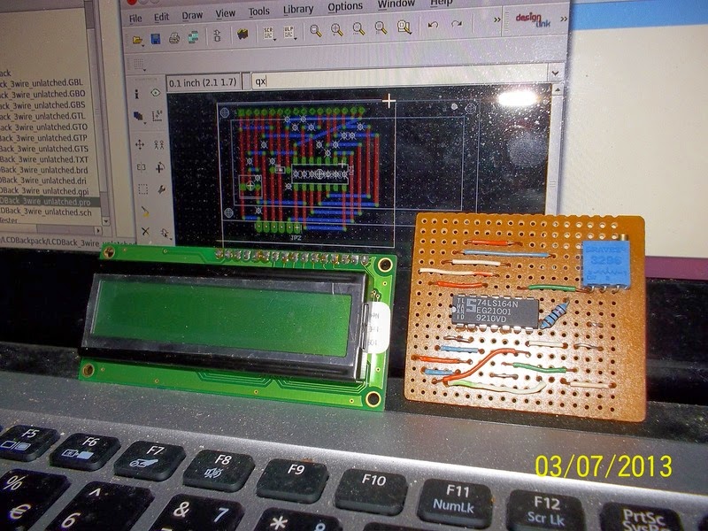
A Serial Backpack for 1602 LCD

I tried to make a serial accessed backpack for a 1602 LCD display suitable for the ardunio.

This one with an unlatched shift register.

Wednesday, November 9, 2011

No Room to Work

We have moved back to the boat, but not really moved in! I 'm not unpacked. This is my desk/ work area/ computer/radio station.
The arduino/ATmel stuff mostly in the boxes to the left. Soldering iron, etc under everything to the right!

Everything that doesn't have an immediate home seems to wind up here. I keep hoping it'll only be a few more days till I can start on this pile. I really need to get the new instruments installed and I'd like to get the wind and solar monitors finished and installed.